- 12/09/2015
- Posted by: rudymore
- Category: Articles
Procedure for NDT Instruments Qualification Tests. Classification of Ultrasonic Testing Devices1.
M. Yu. Tulskiy, D. V. Okunev, I. G. Litvinov
Introduction. Qualification tests are conducted to understand the real capabilities of NDT instruments in detecting defects and to calculate measurement errors for size measurements.
Method. Previous experience has shown that it is impossible to obtain defects with given parameters solely by changing welding conditions. Defects were created mechanically or with an electroerosive method. Size measurements were performed with an X-ray tomograph; its measurement accuracy was confirmed by the results of a metallographic study.
Results.18 types of UT instruments were tested on 5 types of weld grooving. Tests were conducted in accordance with DNV-OS-F-101 and DNV-RP-F118 standards. Welds’ unfoldings with indications of detected defects are presented, along with the average values and dispersion of absolute errors in defect parameter measurements. Classifications of UT instruments are proposed based on hardware implementation and ultrasound application methodology. The results of NDT instrument qualification tests conducted in 2014 were used as the basis.
Conclusions. The completed tests have allowed us to determine the acceptability of each tool for pipeline construction and repair.
Keywords: ultrasonic testing, AUT qualification, AUT validation, pipes, welds, model of a defect, X-ray tomography, UT units’ classification system
Foreword 2022
In 2013, a team of authors from NIPISStroyTEK LLC (in 2016, the enterprise was renamed NVTs STNK «Spektr« LLC) developed, at the request of Gazprom OJSC, the »Temporary Requirements for the Organization of Welding and Assembly Works, Applied Welding Technologies, Non-Destructive Testing of Welded Joint Quality, and the Equipment of Contractor Organizations in the Construction, Reconstruction, and Capital Repair of Gazprom OJSC Main Gas Pipelines.« The non-destructive testing part of this document supplemented the morally outdated STO Gazprom 2-2.4-083-2006 »Instructions for Non-Destructive Methods of Quality Control of Welded Joints in the Construction and Repair of Field and Main Gas Pipelines.«.
«Temporary requirements ...» legalized the use of automated (AUSC) and mechanized (MUSC) ultrasonic inspection systems using transducers on phased arrays and TOFD technology. Introduction in industrial use of AUSC (MUZK) required qualification tests of all types of AUSC units used or planned for use in the territory of the Russian Federation. The tests demonstrated the real capabilities of the control units, and the results of the tests served as a basis for making recommendations on the use of ACM equipment. It should be noted that the fulfillment of a huge amount of work during the tests within 6-7 months and within the budget allotted to us became possible only due to the application of a fundamentally new technology of measuring real dimensions by radiation tomography instead of traditional metallography proposed by M.Y. Tulsky. At present tomography is used in practically all tests of AUZK installations. The methods of manufacturing artificial defects have been significantly improved.
Our enterprise has accumulated extensive experience in conducting tests of ultrasonic flaw detection systems, and the following work was completed up to and including 2022:
- 2011 Validation tests on the Sakhalin-1 project (Client – OJSC «MRTS»);
- 2014: Qualification tests of AUZK and MUZK units (customer - OAO «Gazprom»);
- 2014 Qualification tests of AU Zil and MU Zil units (customer - JSC AK Transneft);
- 2017 validation tests on the South Stream project;
- 2019 Validation of the RotoScan installation for the external transport gas pipeline project from the Novoportovskoye NGKM through the Ob Bay (Client: OAO «MRTS»);
- 2021 Validation of the RotoScan unit for the «Kirin Field Development» project (customer OJSC «SuperStroy XXI»);
- 2022 Validation of the RotoScan unit for the V.I. Graifer Field Development Project (Stage 1 of development). Inter-field pipelines from the V.I. Graifer Field Intermediate Pumping Station (LIS) to the V. Filanovsky Field Intermediate Pumping Station (LIS-2) (multiphase pipeline, gas lift pipeline, water pipeline (Client – OOO LUKOIL-Nizhnevolzhskneft));
- 2022 RotoScan unit validation for the «D33 Field Development with Infrastructure Facilities» project (customer – SuperStroy XXI)
В in July 2023 will come into effect standards 2, developed by NII STNK «Spektr« LLC and VNIIGaz JSC based on »Provisional Requirements...«. The publication of these documents was initially planned for 2019, but due to circumstances beyond our control, it has been postponed indefinitely.
The objective of qualification tests is to determine the real capabilities of non-destructive testing (NDT) installations in detecting defects and calculating errors in defect size measurement.
The qualification test program is based on the requirements of documents [1] and [2]. Data processing is carried out in accordance with the recommendations of [3], [4], and [5].
The tests should include the following stages:
- fabrication of control welded joints (CWJ);
- Manufacture of calibration blocks for setting up equipment;
- preliminary control of the DCS by radiographic method;
- Control of the KSS by UT systems with documentation of the results;
- Performing tests to confirm the operability of control systems (test for repeatability of results, verification of the influence of weld temperature on ultrasonic testing sensitivity, verification of acoustic contact quality);
- measurement of the actual dimensions of discontinuities in a weld;
- determination of the accuracy of estimating discontinuities (absolute measurement errors).
In order for the absolute measurement error values to be reliable, the number of defects in different welded zones must comply with the requirements of Table 1.
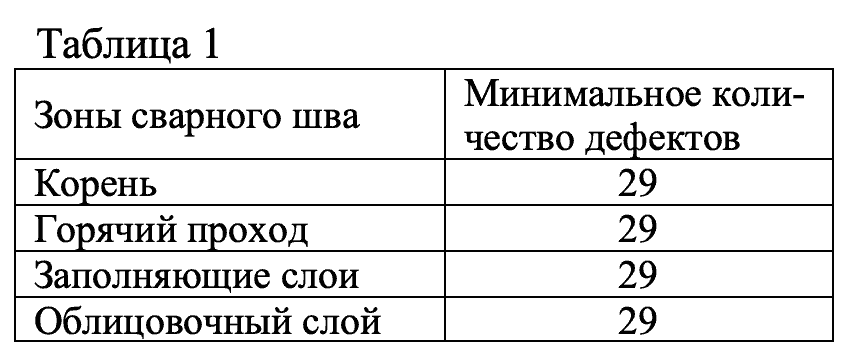
Each weld zone must contain acceptable and unacceptable defects characteristic of the welding method used, defects of artificial origin (~70%of total defects) and natural origin (~30% ). The distances between defects must exceed 20-25 mm so that they can be correctly measured during analysis. The cladding layer includes defects located at a depth of up to 5 mm from the surface.
Based on the preliminary examination and tomography, it is recommended to exclude defects that overlap each other in vertical or horizontal cross-sections of the seam, as they may be measured incorrectly by the UT method.
To measure the actual dimensions of defects, regulatory documentation [1] recommends the metallographic examination method (the «salami» method), in which the defect zone is cut into sections. The height of a defect that appears on a section should be measured with an accuracy of ±0.1 mm, while the accuracy of measuring the extent depends on the step of creating the sections. This method is very labor-intensive, and its application makes it impossible to perform large volumes of work quickly. The problem is solved by using radiation tomography.
To create defects, it is necessary to prepare a defect location map indicating the weld layer numbers, defect types, and parameters.
Previous experience with qualification testing has shown that it is impossible to obtain defects with the specified parameters by changing welding modes. Furthermore, this method does not allow for defects with heights less than the height of the weld metal layer and a length of less than 10-12 mm. Inlaying plates made of non-fusible materials into the weld pool is difficult to implement.
The most effective method for manufacturing defects is mechanical.
Surface defects, such as edge preparation flaws and crack simulators, are created using a milling cutter with sintered diamond discs or by electro-erosion. A carbide insert is placed into the resulting kerf (groove) with a width of 0.4 – 0.5 mm, and the upper edge of the kerf is staked. The experience from qualification tests has shown that it is possible to do without carbide inserts, as the molten metal generally does not fill the grooves.
Pore and cluster defects are simulated by drilling and then center punching holes.
It should be considered that when creating internal defects by mechanical means, it is impossible to obtain a discontinuity of a precisely defined size. The length and height of an artificial reflector are determined by the melt depth of the groove's upper edge, the milling depth, and the milling cutter diameter. Gases rising from the groove during defect welding can create clusters of pores or a vertical funnel-shaped gas channel above the defect and alter its geometry (see Figure 1).
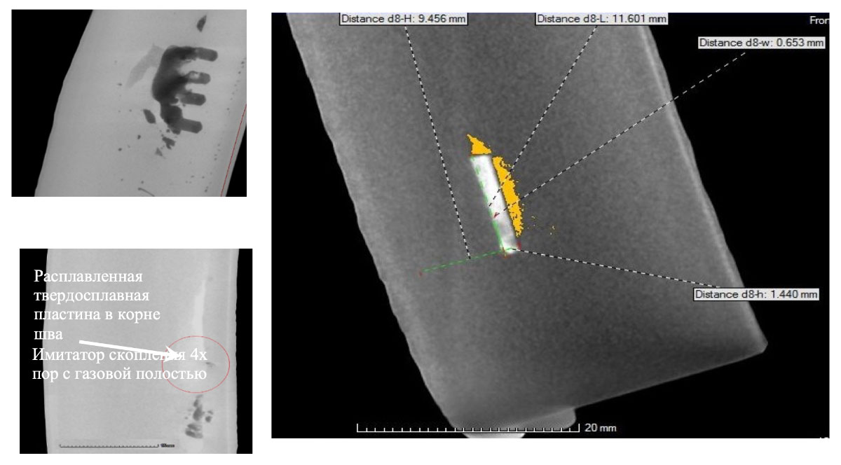
Figure 1 The dimensions of the actual discontinuities do not match the dimensions of the carbide inserts, grooves, and drillings used to create the defects.
Electrical discharge machining of internal defects takes more time but yields more predictable results in terms of defect length and height compared to milling. This method is better suited for manufacturing defect simulators located in the lower layers of a weld, where the use of a milling cutter is impossible, and for surface defects such as undercuts, root lack of fusion, weld overlay cracks, and surface-breaking lack of fusion.
The GE v|tome|x m300 tomographic system (manufactured by GE Sensing & Inspection Technologies GmbH), selected for measuring weld defect sizes, can detect defects as small as 0.1 mm³ and distinguish image details from 0.5 – 1 µm.
For tomographic examination, templates 400-420 mm long and 25-26 mm wide are cut from the weld. When conducting radiation tomography, it is necessary to correctly select the minimum detectable and indicatable volumes of discontinuities and the object rotation step during irradiation. These parameters affect not only the number of detected defects but also the scanning time and, consequently, the cost of the examination. Reducing the volume of detectable defects leads to interference and an excessive amount of information. For instance, when the detectable volume was set to 0.3 mm³, approximately 7,000 indications were obtained in the ring seam of a 1420x26 pipe. When the volume was increased to 0.8 mm³, the number of indications obtained roughly corresponded to the number of indications registered by UT inspection equipment (90-120 indications in the seam).
The accuracy of measurements performed by the tomographic device has been confirmed by metallographic data. The discrepancy in the measurement results of linear dimensions using these methods was 7.7 ± 8.7 µm, and for the depth of occurrence, it was 103.6 ± 47.6 µm, which approximately corresponds to the limit accuracy of measurement in metallographic examination of polished sections.
A comparison of the cost characteristics of metallographic and tomographic inspection (see Tables 2 and 3) shows an almost five-fold advantage for the tomographic method in terms of productivity and a fifty-fold advantage in terms of cost. An increase in the number of defects analyzed increases the cost of metallographic examination and has practically no effect on the cost of tomography.
The use of the tomographic method allows for verification of measurement results and adjustment of defect indication parameters, making the study more accurate. Tomography results can be used to adjust the sensitivity of ultrasonic testing.
| Scan time for a template 400-410 mm long, hours | 4-5 |
| Template scanning data processing time, length 400-410 mm, h | 3-4 |
| Total seam length processed per day, mm | 1200 |
| Number of defects processed per day, pcs | 27-32 |
| Cost of processing one defect, conditional units | 10-12 |
| Minimum number of grinds per defect | 10 |
| Maximum number of grinds performed per day, pcs | 18-22 |
| Number of defects processed per day, pcs | 2–2,2 |
| Cost of processing one defect, conditional units. | 400-500 |
During NDT unit tests, the following must be measured: length, height, and depth of defect occurrence. For units performing rejection based on the amplitude criterion, the length, depth of occurrence, and echo signal amplitude must be measured.
In accordance with the requirements of Gazprom's regulatory documentation, the depth of a defect is not among the criteria for rejecting a weld seam, but its precise measurement is mandatory for equipment used in construction and major repairs. Knowing this parameter allows for the adjustment of welding equipment settings for a specific weld layer.
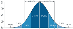
Based on the analysis of tomography data and the results of NDT control obtained by the NDT unit, the average value and variance of absolute errors in measuring defect parameters are calculated. To facilitate the analysis of results, a layout of the weld seam with indications of detected defects (Figure 2) is constructed, along with graphs of the discrepancies in NDT and tomography results (Figure 3). Histograms of the absolute error distribution allow for a comparison of the accuracy of defect parameter assessment by different NDT units. The construction of a histogram of detected discontinuities by depth in the weld seam (Figure 5) makes it possible to determine the acceptability of using the unit in the construction and major repair of pipelines.
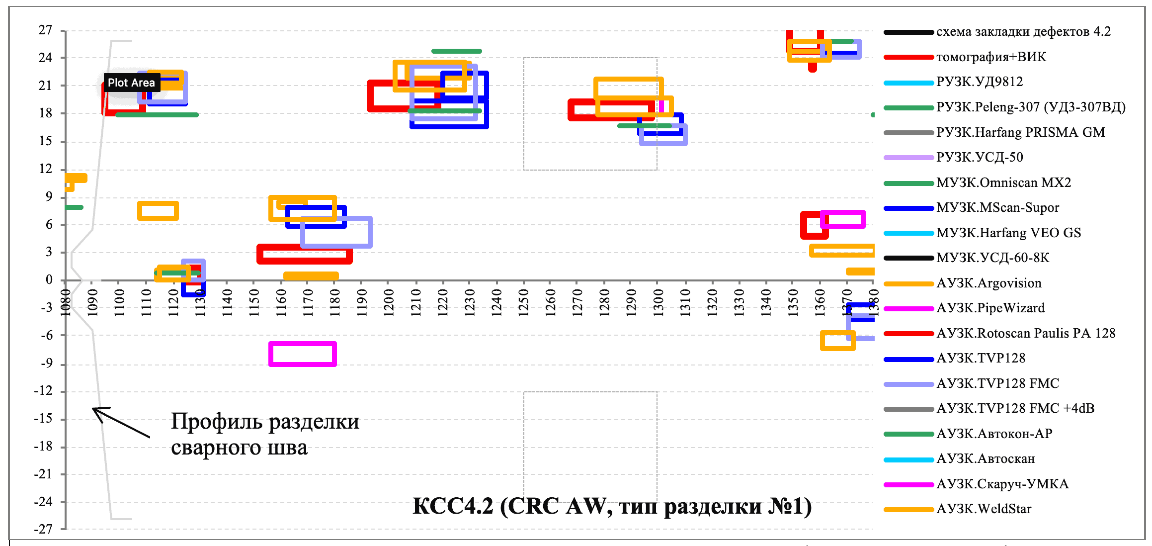
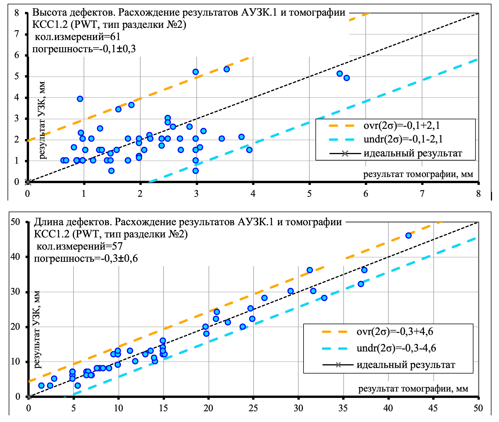
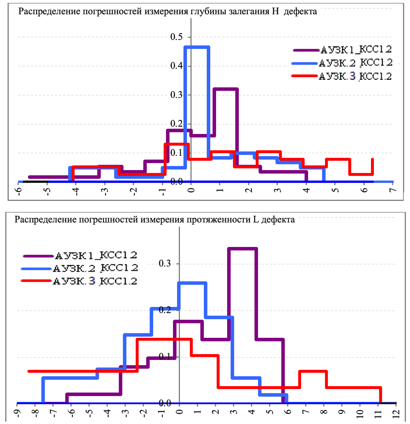
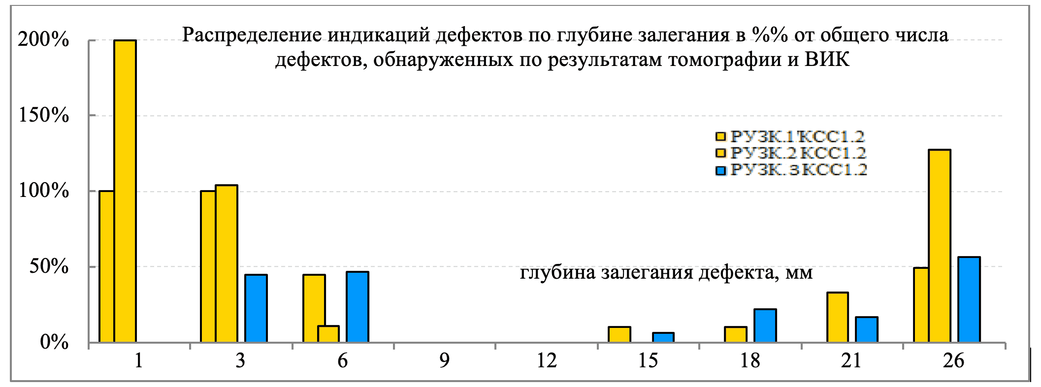
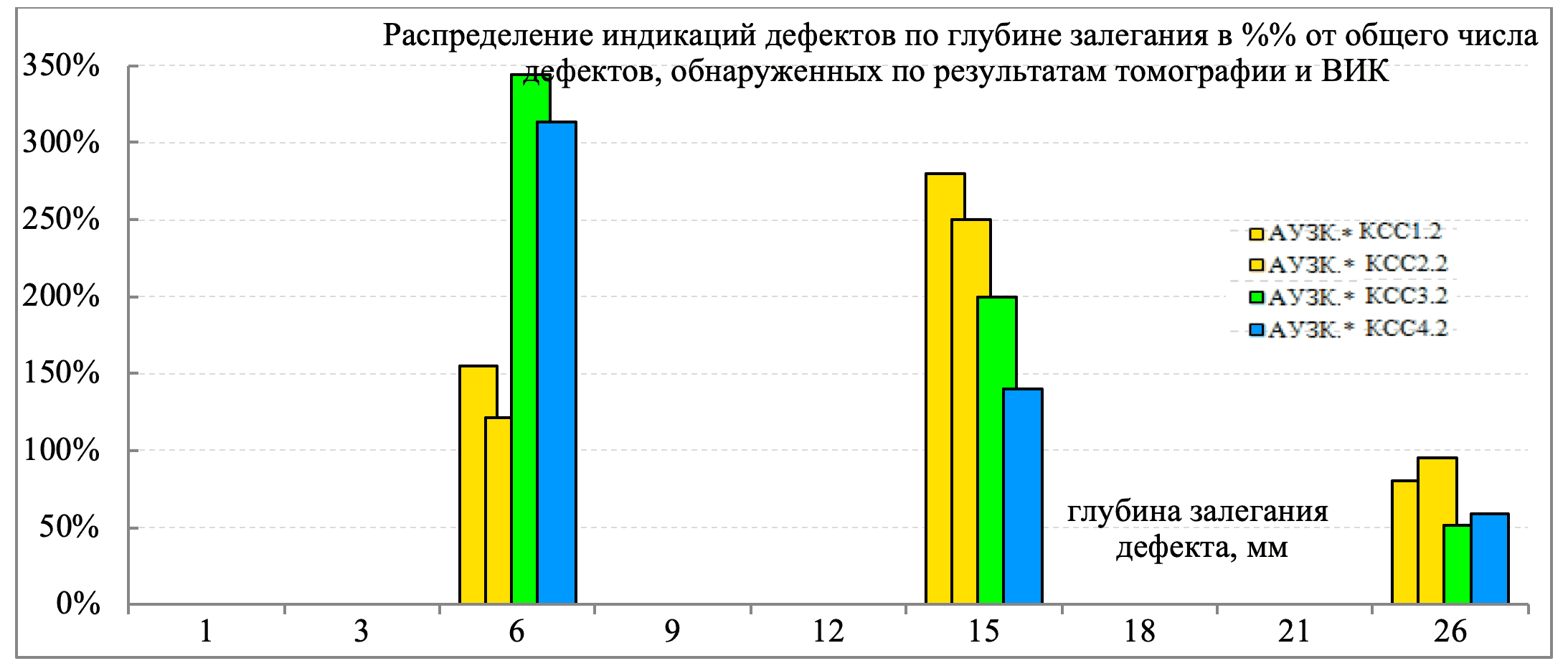
Figure 5 - Histograms of the distribution of detected defects by depth in the test welds
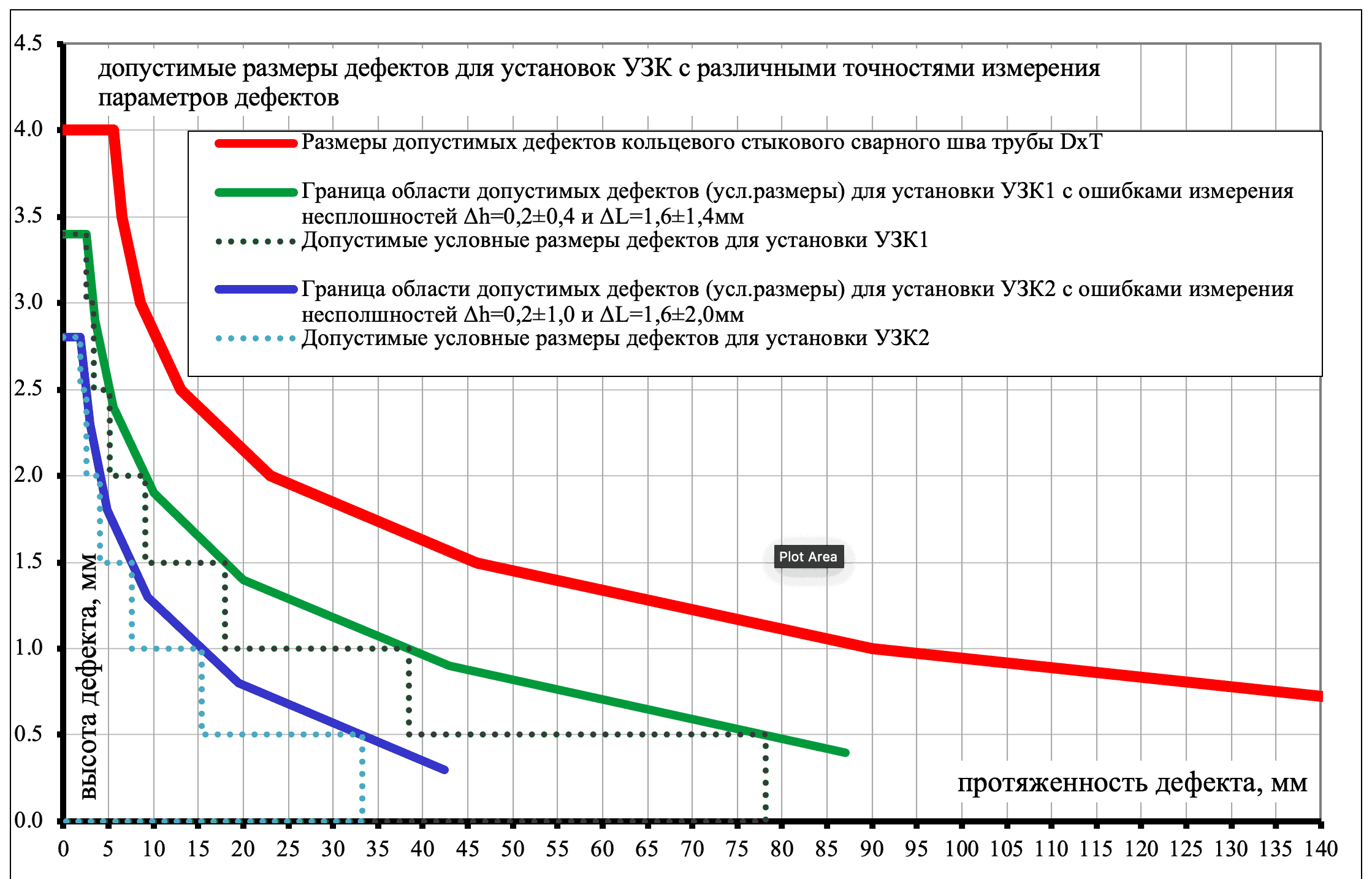
The values of defect measurement errors should be taken into account when developing individual dismantling criteria for each NDT installation. The criteria are developed based on an engineering assessment of the allowable defects for a particular pipe type and pipeline section. Figure 6 illustrates the advantages of using NDT units with more accurate defect measurement indicators. The graph shows the boundaries of the areas of acceptable defects for a pipe ring weld (basic characteristic) and two ultrasonic testing units. Above the boundaries is the area of unacceptable values of defect parameters. Criteria for ultrasonic testing units are obtained by subtracting defect measurement errors from the basic characteristic. The sizes of allowable defects for ultrasonic testing unit 1 with smaller error values are almost twice as large as the allowable sizes for ultrasonic testing unit 2. This means that the number of defects identified as unacceptable according to the results of inspection by a more accurate NDT unit will be lower, and the cost of weld repair will be lower.
The applicability of UT equipment for controlling a specific weld joint preparation must be determined by the results of qualification tests. The inspection schemes implemented by UT equipment must be classified by the hardware implementation of the inspection and the methodology of applying ultrasound. Regulatory documentation must contain requirements for the permissibility of using equipment of a certain class for controlling specific types of welded joints. The functional capabilities of the equipment are proposed to be described by an alphanumeric code.[1].
| 1 | Control using a single acoustic channel [2]. The parameters of the emitted signal do not change during the control. The results of the control are recorded manually at individual points on the controlled object. |
| 2 | Control using multiple acoustic channels. Channel parameters do not change during control. The control results are automatically recorded for the entire controlled object. |
| 3 | Phased array control. The control uses physical focusing of the ultrasonic beam, dynamically changing scanning sequences depending on the weld bevel parameters, sector scanning, and linear scanning at multiple angles can be used. Control results are recorded automatically for the entire inspected volume. |
| 4 | Control using phased arrays. During inspection, software-based (mathematical) focusing of the ultrasonic beam is used. The results of the inspection are automatically recorded over the entire inspected volume. |
Notes
1 The article was published in 2015 in the journals «NDT World» (NDT World, 2015, v.18, no.4) and «Territoriya NefteGaz» No. 12, December 2015, UDC 620.1:622.69)
2 Gazprom Standard 15-1.1-002-2019 Welding and Non-Destructive Testing of Welded Joints. Technologies for Welding Field and Main Gas Pipelines
Gazprom Standard 15-1.3-004-2019 Welding and Nondestructive Testing of Welded Joints. Nondestructive Methods for Quality Control of Welded Joints of Field and Main Gas Pipelines
Gazprom Standard 15–1.5–006–2019 Welding and Non-Destructive Testing of Welded Joints. Requirements for the organization of welding and installation work, welding technologies used, and non-destructive testing of the quality of welded joints during the construction, reconstruction, and major repair of main gas pipelines
[1] The UVK installations allow for flexible reconfiguration of control parameters, therefore a specific installation may have several designation classes
[2] Acoustic channel is characterized by the following parameters: radiation direction, type of radiated wave, radiation focusing parameters
[3] In the zonal method of control, the surface of the weld joint preparation is divided by height into zones, approximately equal to the height of the weld layer. The height of the hot pass and root zones is set in accordance with the parameters of the weld joint preparation. The weld joint filling zone is divided into zones whose height depends on the thickness of the joint being inspected. For each control zone, an individual combined or tandem sounding scheme is formed, which depends on the angle of edge preparation and the conditions for defect detection. Dividing the preparation into zones allows for operational adjustment of the welding head parameters when defects are detected.
TOFD: Ultrasonic Testing Method (Time-of-Flight Diffraction), performed in accordance with the requirements of ISO 16826 and ISO 10863.
Bibliography
- DNV-OS-F-101 Submarine Pipeline Systems. Offshore Standard.
- DNV-RP-F118 Pipe Girth Weld AUT System Qualification and Project-Specific Procedure Validation. Recommended Practice.
- NT Technical Report 394: Guidelines for NDE Reliability Determination and Description.
- NT TR 427. Guidelines for Development of NDE Acceptance Criteria. Nordtest Technical Report
- MIL-HDBK-1823A. Nondestructive Evaluation System Reliability Assessment. (7 April 2009)

Ultrasonic testing technology for welded joints of steel vertical tank walls without removing protective paint coating
The article describes a technology for conducting qualification tests of non-destructive testing equipment for pipeline girth weld joints, which allows for reduced testing costs and shorter timelines. A classification system for ultrasonic testing units based on their functional capabilities is proposed.
02/10/2008-
Technology for Conducting Qualification Tests of Non-Destructive Testing Devices. Classification of Ultrasonic Testing Devices
The purpose of qualification tests is to determine the actual capabilities of non-destructive testing (NDT) units in detecting defects and to calculate the measurement errors of defect sizes.
12/09/2015 -
Evaluation of Ultrasonic Flaw Detection Equipment Validation Results
Qualification and validation tests of automated (mechanized) ultrasonic testing (AUT / MUT) systems are carried out to confirm the technical characteristics of the systems and to assess their suitability for quality control of welded joints on a specific project.
20/03/2023