Qualification and validation testing of automated (mechanized) ultrasonic testing (AUT / MUT) systems are carried out to confirm the technical characteristics of the systems and to assess their suitability for quality control of welded joints on a specific project. Requirements for conducting tests are contained in DNV GL documents, but the issues of adjusting the quality assessment criteria for welded joints based on test results are vaguely stated, and some of the criteria for successful completion of validation tests turn out to be, upon closer examination, unachievable. The article proposes a method for evaluating the success of validation tests.
Evaluation of the AUT validation results
Automated (mechanized) ultrasonic testing units (AUT/MUT) qualification and validation are performed to confirm the technical characteristics of the units and to assess their suitability for quality testing of specific project welds. DNV GL documentation provides guidelines for the qualification and validation of automated ultrasonic testing units. However, the issues of adjusting the criteria for evaluating the quality of welded joints (ECA) based on test results are superficially addressed, and the criteria for validation success are, upon closer inspection, unachievable. This article proposes a method for assessing the success of validation.
Qualification and validation testing of automated (mechanized) ultrasonic testing (AUT) for girth butt welds are carried out in accordance with DNV GL-ST-F101 (app. E) and DNV GL-RP-F118 on test welds with artificial and natural defects. The list of tests performed during testing is provided in Table 1. Table 1 – Installation tests of the AUZK performed during trials
Test ID | Test Name | qualification test. | valid. test. | Notes |
|---|---|---|---|---|
| 1 | Defect detection rate check by UT testing equipment3 | + | + | Based on the results of ultrasonic inspection of KSSh: - Errors in estimating the geometrical parameters of defects (height, depth, length) are calculated; - The detection capabilities for pores and inclusions are assessed; - Probability of Detection (PoD) is calculated during qualification testing; - Calculated values of unacceptable defect parameters are corrected. |
| 2 | Checking the influence of weld bead temperature on ultrasonic testing sensitivity4 | + | The check is performed to determine the maximum allowable temperature difference between the calibration sample and the inspected weld, at which the inspection sensitivity changes by no more than 2 dB. By agreement of the parties, this test may not be performed, but in this case, during ultrasonic testing, the temperature difference between the calibration block and the inspected weld must not exceed 15 °C. | |
| 3 | Acoustic contact quality check6 (AK) | + | The check is carried out to confirm that: - until the alarm is triggered, the sensitivity of the ultrasonic flaw detector changes by no more than 4 dB compared to the initial setting; - when the couplant disappears, the system will not miss an unacceptable defect of the minimum size. The criteria for the disappearance of acoustic contact must be established based on the number of simultaneously triggered acoustic contact monitoring channels and the criteria for evaluating the acceptability of detected discontinuities (the permissible length of the acoustic contact loss zone should not exceed the minimum length of an unacceptable defect, and the distance between acoustic contact loss zones should not be less than the length of an unacceptable defect). | |
| 4 | Repeatability of control results verification7 | + | +8 | The check is performed on a calibration block or CCC to confirm the operational capability of the unit in various spatial orientations («12 o'clock» and «6 o'clock») on the pipe. |
The purpose of the qualification tests is to confirm the following capabilities of the AUZK installation:
- detect unacceptable defects with a probability of at least 85% at a 95% confidence interval9 ;
- to evaluate geometric parameters (height, depth, length) and the position of discontinuities in the seam with specified accuracy.
Based on the results of the qualification tests, the PoD (Probability of Detection) is calculated – the smallest defect height detectable with 90% probability% at a 95%% confidence interval (90|95% PoD).10. This value should not exceed the height of the minimum unacceptable defect and is the primary characteristic to consider when evaluating the suitability of a specific ultrasonic testing (UT) unit for use on a project.
By agreement of the parties involved in construction, the quality of welded seams can be assessed according to any of the following criteria:
- according to the criteria given in Table E-1 or E-2 DNV GL-ST-F101;
- in accordance with ECA (engineering critical assessment).
When assessed against the criteria provided in Table E-1 or E-2, the UT equipment is considered to have passed the qualification tests and the seam weld inspection technology is deemed suitable for application if, as a result of comparing UT data and actual defect sizes, the following is established:11:
- The random error in the height estimation does not exceed ±1 mm, while the mean error (systematic error) does not exceed 0.8 mm.12;
- The random error in the depth estimation does not exceed ±2 mm;
- The random error in the length estimate does not exceed ±5 mm.;
- probability of defect rejection (PoR) of 1 mm in height exceeds 85% at a confidence interval13 equal 95%.
In par. E.8.4.1 — E.8.4.3 DNV GL-ST-F101, the following success criteria for qualification testing of Automatic Ultrasonic Testing (AUT) installations are established, when evaluating the quality of welds based on ECA criteria:
- errors do not exceed reasonable limits14;
- The systematic error should not exceed 0.8 mm15.
Given that these requirements are stated using the vague terms «excessive oversizing» and «systematic over sizing, i.e. over sizing on average,» they cannot be considered clear and acceptable for work. However, it is possible to understand what the author intended to convey. For simplification, it can be assumed that the success of qualification tests when using the ECA criteria should be assessed in accordance with the requirements established for projects with weld quality assessment according to the criteria specified in tables E-1 and E-2 of DNV GL-ST-F101.
Validation tests of a specific ultrasonic testing unit must be performed before starting work on the project. The objective of the tests is:
- Confirmation of the detection capability for the smallest critical (unacceptable) defect by a specific ultrasonic inspection unit.16, performing control in accordance with the procedure developed for this project;
- demonstration that the error in estimating the geometric parameters of defects found in the weld is within specified limits.
During qualification tests, between 91 and 122 defects must be measured depending on the type of weld preparation.17: not less than 29 defects for each zone of the weld (root, hot pass, filling passes, capping pass). During validation tests, it is sufficient to measure at least 29 defects18 for the entire seam.
From JSC "KCS", controlled by AUZC, radiographic19 and other additional methods of NDT, templates with defects are cut out, the real dimensions of the defects are measured
by metallographic method or by radiation computed tomography method20. On
Based on the data from the AUZV and actual size measurements, the detection probability is calculated.
defects21) and errors in estimating their geometric parameters22):
where Xi is the error in estimating the size of the i-th discontinuity;
Xi_AUT conditional size of the i-th discontinuity based on UT results (AUT);
XI_real real size of the i-th discontinuity based on tomographic measurement results or
by metallographic method;
Xm Average defect size estimation error (systematic error);
delta standard deviation (root mean square deviation) 23)
ΔX confidence interval for the size of heterogeneity (random error);
XError error in estimating defect size;
N number of dimensions (number of discontinuities);
t(P, N-1) Student's t-coefficient for confidence interval P and N measurements.
Equality (5) means that the true size of the discontinuity is in the interval
[Xm — ΔX;
Xm + ΔX] with a probability of 95 %.
The ECA values are calculated based on strength characteristics, geometric
parameters and operating conditions of pipes used on the project. Calculated values of height and
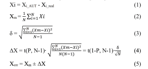
The lengths of allowable defects should be reduced24 on (Xm – 1.64 * δ) — on the magnitudes of the errors
estimates of the defect height and length that ensure no more than a 5% probability that
the defect size will be underestimated (probability of missing (rejecting) the smallest
unacceptable defect will not exceed 5%). The meaning of the value (Xm – 1.64∙δ) is explained by Figure 1.
Corrected ECA` values are used to assess the acceptability of discontinuities.,
detected on a specific project using a specific ultrasonic testing unit25.
The corrected ECA’ values define the permissible conditional defect sizes,
detected during transesophageal echocardiography.
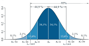
Figure 1 – Distribution of errors in the estimation of geometric parameters of discontinuities,
obtained from the results of the AUZK unit tests. Xm – average error value.
To the right of the value (Xm – 1.64∙δ) lie 95% percent of the error values.
Figure 2 shows an example of adjusting the calculated ECA characteristic based on the results
tests. For the installation of a certified AUZK, acceptable conditional values
defect sizes are under the corrected characteristic (green curve).
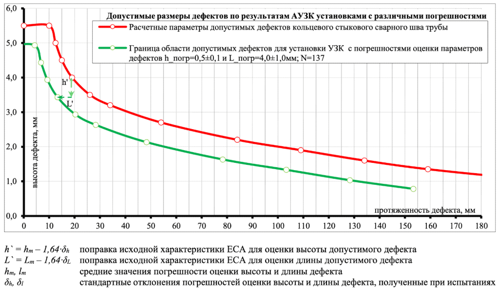
Figure 2 – Example of adjusting the calculated characteristic ECA by the amount h` in height and L`by the length of the allowable discontinuity
The corrected characteristic is the result of a bias in the calculation.
ECA characteristics (red curve) down at h’ = h m – 1.64∙δh and to the left to L' = Lm – 1.64 ⋅ δL. Understood.,
The lower the error in estimating the parameters of discontinuities obtained from tests
The adjusted criteria will be less stringent compared to the calculated ones.
and the lower the probability of weld rejects will be.
Section E.8.4.2 of DNVGL-ST-F101 requires the ECA characteristic to be adjusted based on the results
qualification tests, and section E.9.2.9 – based on the results of validation. ECA adjustment
should be carried out based on the results of tests of a specific ultrasonic testing unit, conducted before
the start of a specific project.
DNV GL standards do not explicitly contain requirements for adjusting criteria,
provided in tables E-1 and E-2 of DNV GL-ST-F101, but it is logical to assume that the values,
the ones listed in them should be adjusted in the same way as the ECA characteristic.
In accordance with par. I200, App. E, DNV OS-F101-201326 and par.9.3 DNV GL-RP-F118 is considered,
that the validation tests passed successfully if «..the [AUZK] unit identifies the smallest
an unacceptable defect for a specific project. This is achieved by detecting all 29
defects and demonstration that the error of estimating the parameters of these 29 defects is not
exceeds the established accuracyqualified accuracy)» 27. Term qualified accuracy Indicates
that the error in estimating the parameters of discontinuities should not exceed the values,
obtained during qualification trials. Is this possible?
Root mean square deviation values obtained in qualification (δq) and
validation (δv) tests can differ by tens of percent. Even in cases where
An array of 29 values is randomly selected from the array obtained from
qualification tests and the root mean squares for these arrays, it would seem
should have close values, it is impossible to give an accurate estimate of the difference between them, nor is it
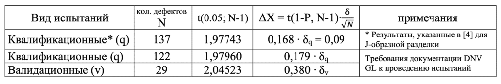
The greatest influence on the magnitude of the random error ∆X is exerted by N — the number
analyzed discontinuities (formula 4). The values of N, t(1-P, N-1) and ΔX, obtained when
qualification and validation tests are presented in the table, given
the number of defects, the values of ∆X will differ by approximately two times (formula 6):
Conclusion:
- The random errors ΔX in the defect parameter estimates obtained during validation will be
approximately 2 times more errors than those obtained from the qualification results
trials28. This means that the success criteria for the validation tests, specified
in par.9.3 DNV GL-RP-F118 are unattainable. - For a correct comparison of validation and qualification test results
A reduction factor K is needed to correct the random values.
errors ΔX obtained during validation:

where v, q are indices indicating that the corresponding quantities were obtained as a result of
validation or qualification testing
Nq and Nv- number of defects investigated in qualification and validation
trials
1 par. E.8.2.1, E.8.3.1 DNVGL-ST-F101 (ed. 2017)
2 Section 4 DNVGL-RP-F118 (ed. 2017)
3 par. E.8.8.9, E.8.8.10 DNVGL-ST-F101 (ed. 2017)
4 par. E.8.6.1, E.8.8.7, E.8.8.8 DNV GL-ST-F101 (ed. 2017)
5 sec. 11.1 EN ISO 17640-2017
6 pars. E.8.8.11, E.8.8.12 DNV GL-ST-F101 (ed. 2017)
7 par. E.8.6.1, E.8.8.5, E.8.8.6 DNV GL-ST-F101 (ed. 2017)
8 par. E.9.2.2 DNV GL-ST-F101 (ed. 2017) does not require mandatory performance of this type of testing. By agreement of the parties, the tests may not be carried out.
9 par. E.8.4.3 DNV GL-ST-F101 (ed. 2017) App. E
10 par. E.8.4.1 DNV GL-ST-F101 (ed. 2017)
11 par. E.5.4.1, E.8.4.1 — E.8.4.3 DNV GL-ST-F101 (ed. 2017) App. E: the specified criteria apply if the error in the defect height assessment does not exceed ±1 mm based on the qualification test results. The standard does not specify which error is meant: systematic (Xm), random (ΔX), or the interval [Xm — ΔX; Xm + ΔX], but most likely, our interpretation of the DNV GL requirements is correct
12 In accordance with par. E.8.4.2, the value of «systematic over sizing» shall not
exceed 0.8 mm, and it is unclear whether this means that Xm ≤ 0.8 mm (while the lower bound of Xm is not defined)
or the value of Xm should be in the range [-0.8; 0.8].
13 See Note 7 to Table E-1 of DNVGL-ST-F101 (ed. 2017). Probability of Detection (PoD) is calculated
only on qualification tests. Exclusion of defects up to 1 mm in height from the calculations is due to the fact that defects
heights less than 1 mm cannot be measured by UT methods, even though the presence of a defect can be detected.
14 This means that no specific error tolerances have been established.
15 The standard does not specify which parameters the estimation error refers to. Most likely –
On the systematic error of measuring the height of a defect
16 par. E.9.2.9 DNVGL-ST-F101 (ed. 2017) and sec. 9.3. DNVGL-RP-F118. The wording «smallest critical defect»
implies a defect, the smallest in height
17 See Table E-3 DNV GL-ST-F101 (ed. 2017) and Table A-1, Table A-2, Table A-3 DNVGL-RP-F118 (ed. 2017).
18 In clauses E.8.1.1.1, E.9.1.6, and E.9.2.3 of DNV GL-ST-F101 (ed. 2017), it is stated under what conditions validation can be
performed on a reduced program based on the analysis of 12 defects. In this case, each weld zone (external
(near-surface, internal near-surface, fill zone) must contain at least three defects.
19 Radiography is used as an auxiliary NDT method for rejecting defects that do not meet
to the test program requirements, for example, stacked imperfections by height
or length. As additional methods for detecting surface defects, DNV GL standards
magnetic particle, penetrant, electromagnetic (ACFM), or eddy current methods are recommended, and for
identification of internal defects – manual UT of welds and immersion UT of templates. It should be noted that
The effectiveness of ultrasonic testing in detecting vertically oriented defects or lack of fusion along the edge in welds with
dressing (5° - 16°) will be practically zero, and the benefit of immersion UT is generally questionable. When prescribing
when considering methods for additional QC and assessing their necessity, it should be kept in mind that the objective of this QC is to confirm
the presence of defects in the weld joint and, in the case of a welded joint, in the immersion ultrasonic inspection, - clarification of their length to reduce the scope of metallography work. To solve this problem, the tested AUK (at least only TOFD channels, if a calibration block is missing) can be used instead of the ultrasonic inspection. If the measurement of the actual defect sizes is planned to be performed by the radiation tomography method, then there is no particular need to clarify the defect length.
20 In accordance with par. 5.1 of DNV GL-RP-F118, metallography can be replaced with another examination method that ensures the specified accuracy of measuring the geometric parameters of SCC defects. Since 2014, by agreement with Customers, LLC «RIFC STNK «Spektr» has been performing radiation computed tomography instead of metallography, which significantly reduces the testing time and, if necessary, allows verification of the correctness of defect size measurements.
21 Defect detection probability is calculated only during qualification testing. The calculation is performed in accordance with NT Techn Report 394. Guidelines for NDE reliability determination and description
22 The calculation of the error in estimating defect parameters is performed according to GOST R 8.736-2011.
23 Term in accordance with GOST R 8.736-2011
24 see par. E.8.4.2 DNV GL-ST-F101 (ed. 2017), the document uses the concept of «under sizing error tolerances giving less than or equal to 5% probability shall be determined and used in relation to any ECA specified defect sizes» - «correction of ECA characteristics, ensuring no more than 5% probability of underestimating defect size»
25 See par. D.2.10.4 DNV GL-ST-F101 (ed. 2017)
26 DNV GL-ST-F101 (ed. 2017), unlike DNV OS-F101-2013, does not explicitly contain success criteria.
for conducting validation tests. DNVGL-ST-F101 (ed. 2017) states:
- par. E.9.1.1: validation must show that the difference between the characteristics obtained from
qualification and validation tests are within reasonable limits;
- para. E.9.2.1: During validation, it is necessary to confirm the detectability of the smallest critical
(unacceptable) defect for a specific project.
In par. E.8.2.1 of DNVGL-ST-F101, it is stated that qualification tests shall be carried out in accordance with
DNV GL-RP-F118. Regarding validation tests, there are no requirements, but it is logical to assume,
both the order of conducting and the criteria for successful testing should be similar.
27 Validation success criteria in accordance with par. I200, App. E, DNV OS-F101 (ed. 2013) and par.9.3 DNV GL-RP-
F118: «The purpose of the validation is to verify that the project-specific AUT procedure capability is adequate for detection of
the smallest project-specific critical defect. This is obtained by demonstrating detection of all 29 defects and that these 29 defects
has been sized and positioned within the qualified accuracy. If this is achieved, the project specific AUT procedure is validated and shall be accepted.»
![]()
To calculate the coefficient K, the value of N should be usedq, as indicated in the report by
results of the general tests [4]. When adjusting the random error, it is necessary to
remember that the ΔX obtained during validation tests should not be less than the value,
obtained during qualification tests. The random error ΔX` of the size estimate
defects from the validation results to calculate as:
![]()
Literature
DNV-OS-F101 Submarine Pipeline Systems (October 2013)
DNVGL-ST-F101 Submarine Pipeline Systems (October 2017)
[3] DNVGL-RP-F118 Pipe Girth Weld Automated Ultrasonic Testing (AUT) System Qualification and Project-Specific Procedure
validation (May 2017)
DNVGL General Qualification of the Applus+ RTD Rotoscan AUT System. RTD. Report no.: 2009-
4129/ 280527 Rev 03, 2019-03-28
ENIQ (2007) European Methodology for Qualification of Non-Destructive Testing (3rd edition). EUR
17299 EN, Luxembourg.
[6] GOST R 8.736-2011 State system for ensuring the uniformity of measurements. Measurements
Direct multiple. Methods of processing measurement results. Basic provisions
NT Techn. Report 394 Guidelines for NDE Reliability Determination and Description (Approved)
1998.04, NordTest project number: 1303-06
[8] Nondestructive Evaluation and Quality Control: Quotative Nondestructive Evaluation. ASM Metals
Handbook. Vol.17 ASM International. 4th printing, Jan/1996.
ASME Sec. V Art 14, ASME Sec III Appendix VIII, ASME Sec VIII
[10] Statistical Test Analysis Tools for Ultrasonic Systems. User Guide. © Materials Research Institute 2005

Ultrasonic testing technology for welded joints of steel vertical tank walls without removing protective paint coating
The article describes a technology for conducting qualification tests of non-destructive testing equipment for pipeline girth weld joints, which allows for reduced testing costs and shorter timelines. A classification system for ultrasonic testing units based on their functional capabilities is proposed.
02/10/2008-
Technology for Conducting Qualification Tests of Non-Destructive Testing Devices. Classification of Ultrasonic Testing Devices
The purpose of qualification tests is to determine the actual capabilities of non-destructive testing (NDT) units in detecting defects and to calculate the measurement errors of defect sizes.
12/09/2015 -
Evaluation of Ultrasonic Flaw Detection Equipment Validation Results
Qualification and validation tests of automated (mechanized) ultrasonic testing (AUT / MUT) systems are carried out to confirm the technical characteristics of the systems and to assess their suitability for quality control of welded joints on a specific project.
20/03/2023